
Whilst now largely obsolete and confined mostly to legacy systems, for many years IDE hard drives were standard within desktop PCs. This short guide looks at the history, identification and setup of these drives.
A brief history
The first IDE drives appeared in 1986 after the standard was developed by Western Digital, initially appearing in HP Compaq PCs. Unusually for the time the hard drive controller was integrated into the drive which brought a number of advantages. It made it easier to standardise hard drives and also made hard drives less complicated and subsequently more companies were able were able to produce them. This drove the prices of the drives down and as a result they were widely adopted in the burgeoning home PC market.
Whilst IDE was initially designed to be used with hard drives the introduction of ATAPI allowed other devices such as optical drives to use the interface. This worked by allowing the interface to carry SCSI commands.
Several revisions and improvements took place to the standard, including Ultra DMA which improved transfer speeds. However in the early 2000s SATA was announced designed to address the limitations of the IDE/PATA standard. In 2003 SATA-1 was released and the desktop market started to shift towards these drives.
By the end of 2013 SATA had been the dominant standard in desktop PCs for many years and both Western Digital and Seagate had stopped the manufacture of IDE drives.
IDE vs SATA
IDE drives have almost entirely been replaced by SATA drives in newer machines and there is almost no reason to choose to use them given the option. Firstly SATA drives are quicker. IDE drives operate a parallel interface with all signals needing to arrive at the same time, by contrast the serial interface of SATA allows considerably faster data transfer. IDE drives can only reach speeds of 1.33Mb/s where as the slowest SATA standard offers a transfer rate of 1.5Mb/s. SATA-3 can transfer at more than 4 times the speed with a transfer rate of 6Mb/s.
SATA drives are also easier to setup, with an IDE setup requiring correct positioning on the cable and the setup of jumpers on the drives. SATA drives simply plug straight in, connected by their data cable to the motherboard with no similar configuration. SATA cables are also much narrower allowing greater airflow within the case in contrast to the wider IDE cables. In addition (with the relevant hardware/software configuration) SATA drives can support hot swapping whereas IDE ones do not.
Identifying an IDE hard drive

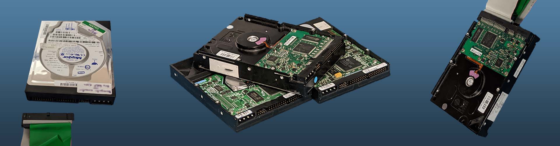
The easiest way to identify if the drive in your desktop PC is IDE is by the connector. As shown in the image above an IDE drive has 2 connectors- the large IDE data interface connector on the left and the 4 pin Molex power connector on the right. This is in contrast to the flat data and power connectors found on SATA drives. In between the connector’s on an IDE drive are the jumpers which we will return to when explaining how to set up an IDE drive.
If you don’t have access to the drive but know the manufacturer’s part number sites sites such as hdsentinel.com provide a wealth of information about the drive model. This includes it’s interface as well as other information such as speed and capacity.
Installing an IDE drive

The end of the IDE cable with the single connector is plugged into the motherboard. The end with 2 connectors is where the drive(s) are placed.
The first thing to do with the drives is set the jumpers correctly. If it is a single drive it can be set as the master, this will then be plugged into the end connector. If you have 2 drives the master is set in the same way, the second drive must have its jumper configuration set to slave and is then plugged in on the inner of the 2 connectors.
The main drive with the operating system installed is normally chosen as the master, with the slave drive offering additional storage or operating as a backup.
Later IDE drives also support cable select, where the master and slave drive are chosen by their position on the cable. In order for this to work you need a compatible cable and to set both drive’s jumpers to “cable select”.
When plugging in the cable the red line on it can be used to make sure it is the right way round. The line corresponds to pin 1 and on IDE hard drives this plugs into the side nearest the power connector.
Looking to purchase IDE drives? Our store carries a selection of both 2.5″ and 3.5″ drives. You can browse them here.


